Motorization of a KEMAR head
Overview
In this section, we propose a non-intrusive mechanism to motorize the head rotation of a KEMAR HATS. It includes a silent brushless motor and two limit sensors to constrain the admissible rotation range, assembled with designed aluminium parts that preserve the original neck thickness and shape. The mechanism, placing the motor inside the torso, is visible on Fig. 3.
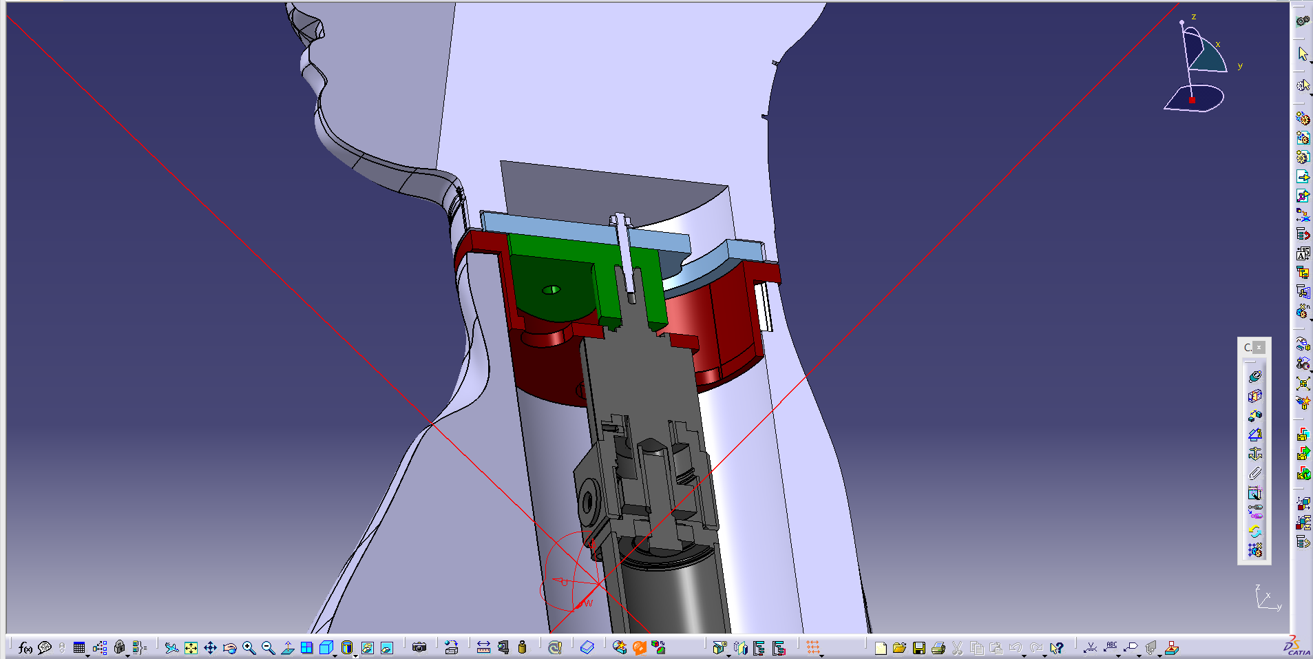
Fig. 3 CAD view of the proposed mechanism and its integration in a KEMAR HATS
The instructions below detail how to set up this mechanism to get a motorized KEMAR head.
Assembly of the mechanism
For this part, you will need:
- A KEMAR HATS Type 45BB-2
- A 100W brushless DC motor SA01ACN-8 from A2V, with gearhead PGE12/1 i=9
- Two proximity optical sensors VTF180-2N41112 from Sick
- The designed aluminium pieces (see instructions below)
- An anti-reflection adhesive film
- M4 screws
The steps to assemble the mechanism are as follows:
You first need to manufacture the three aluminium pieces, visible in blue, red and green on Fig. 3. CAD models are available in the kemar-hardware repository, in folder
motorized-neck/mechanics. Filehead.stpis the blue piece, fixed to the head. Filetorso.stpis the red piece, fixed to the torso. Filerotation.stpis the green piece, fixed to the rotating axis of the motor. Last, fileassembly.stpshows the pieces assembled together with the motor, it can help having a look at it while you mount the mechanism.Remove the original part below the head and place the new head piece (blue). Keep and reuse the same screws. As this part will be placed above the proximity optical sensors, an anti-reflection adhesive film must be stuck to prevent any reflection (see Fig. 4). The two audio cables can be passed through the arc-shaped hole. Screw two plastic screws for head alignment inside the head as shown on Fig. 4.
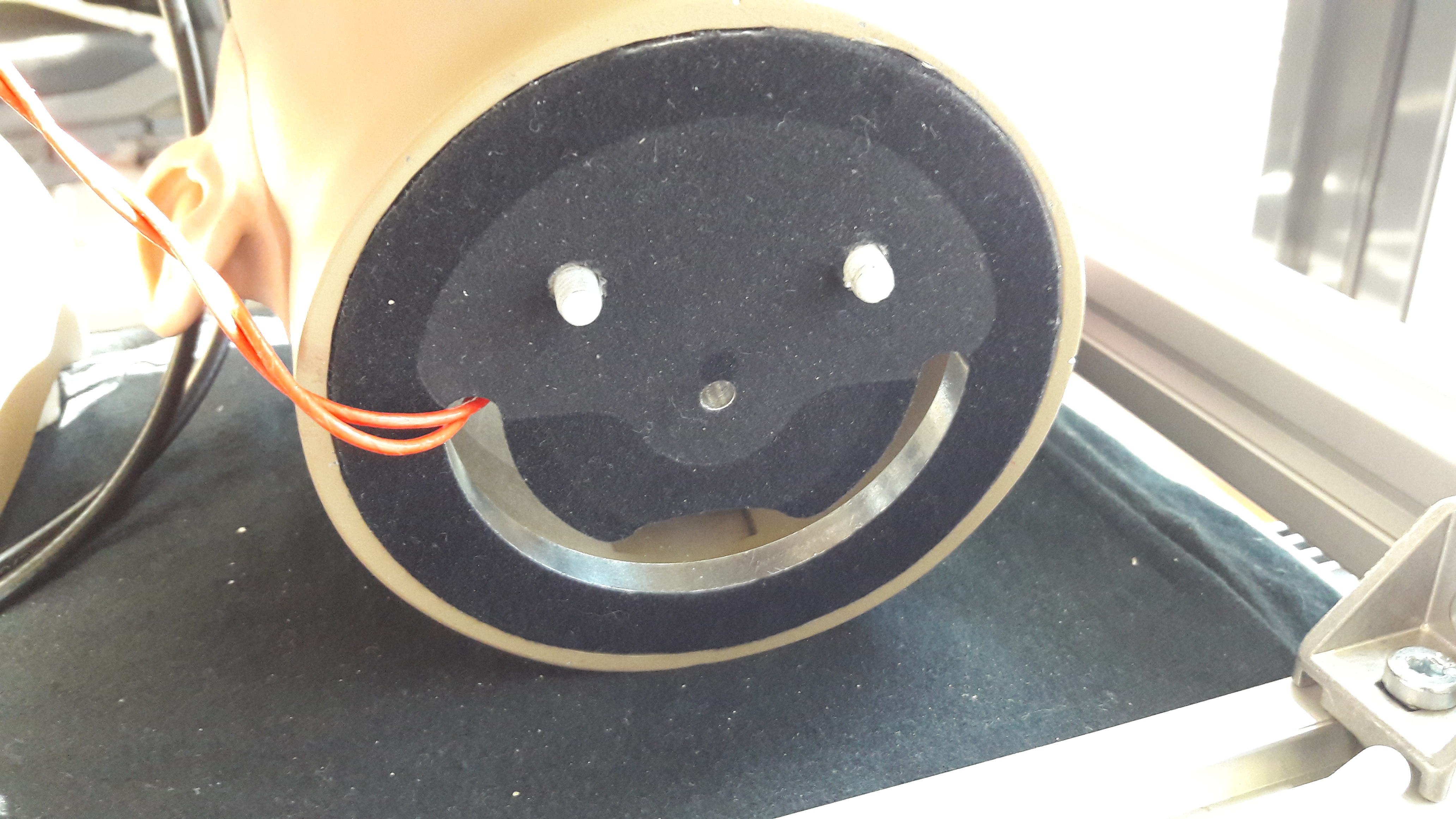
Fig. 4 KEMAR head with the new piece in place, the anti-reflection film fixed, and the plastic screws.
Assemble the motor to the new aluminium part that will be fixed to the torso (red) with four M4 screws. The arc-shaped hole will go at the rear of the new neck.
Place the two optical sensors into the dedicated holes (one on front, the second on left side). The nuts provided with the sensors are too big to be placed direcly. Nuts must be rounded first to be integrated.
Position the rotating piece (green) on the motor shaft (Fig. 5). There is a groove on the shaft. Align the two hexagonal screws with the groove and fix them. On this aluminium piece (green), the two holes will fit with the corresponding plastic screws present into the head piece. Countersunk holes (Fig. 6) correspond to a previous version with plastic screws fixed on the rotating part. For next designs, integrating plastic screws into the head is better because this enables a tighter coupling of the head and the rotating part.
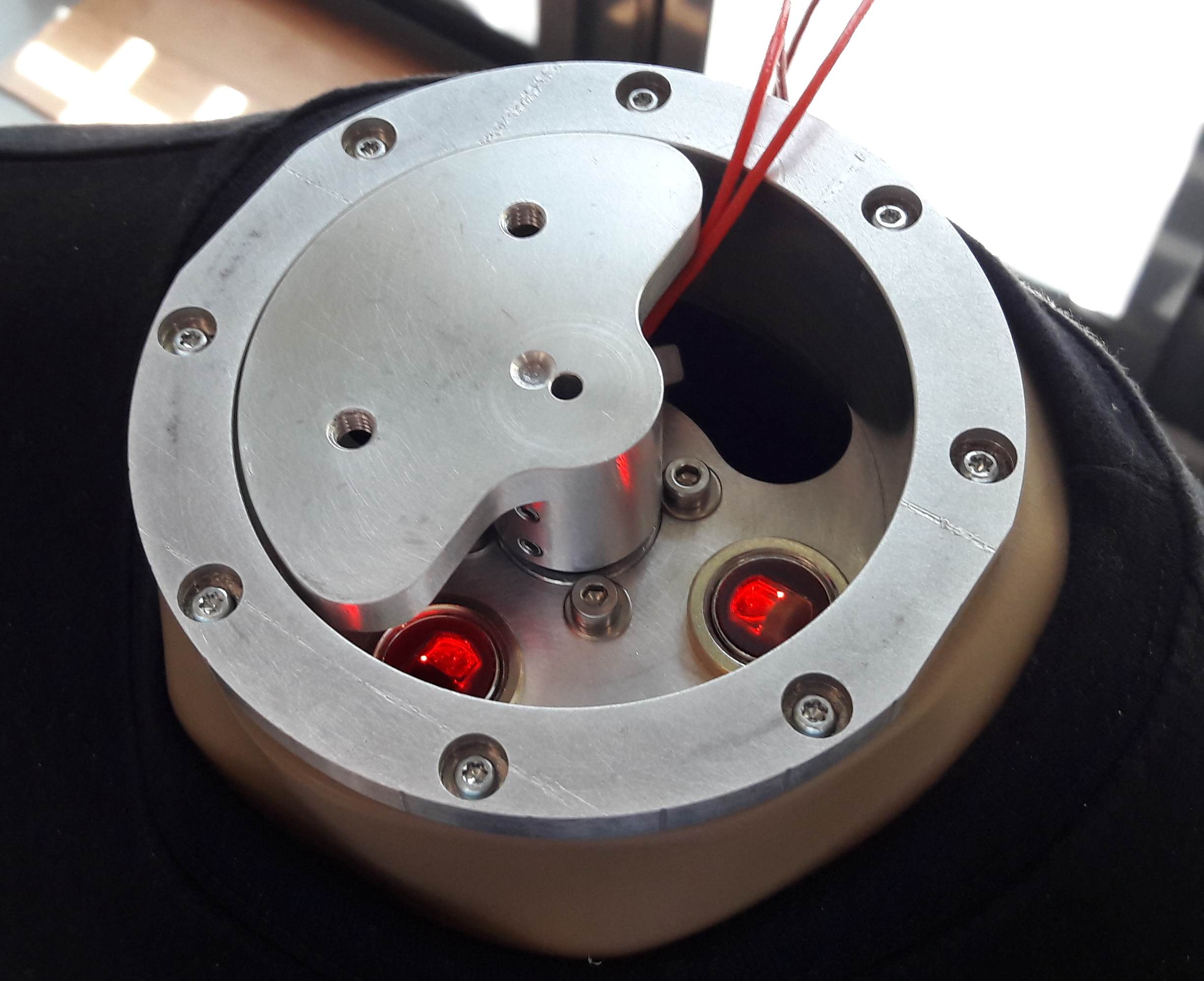
Fig. 5 KEMAR torso with the new mechanical devices
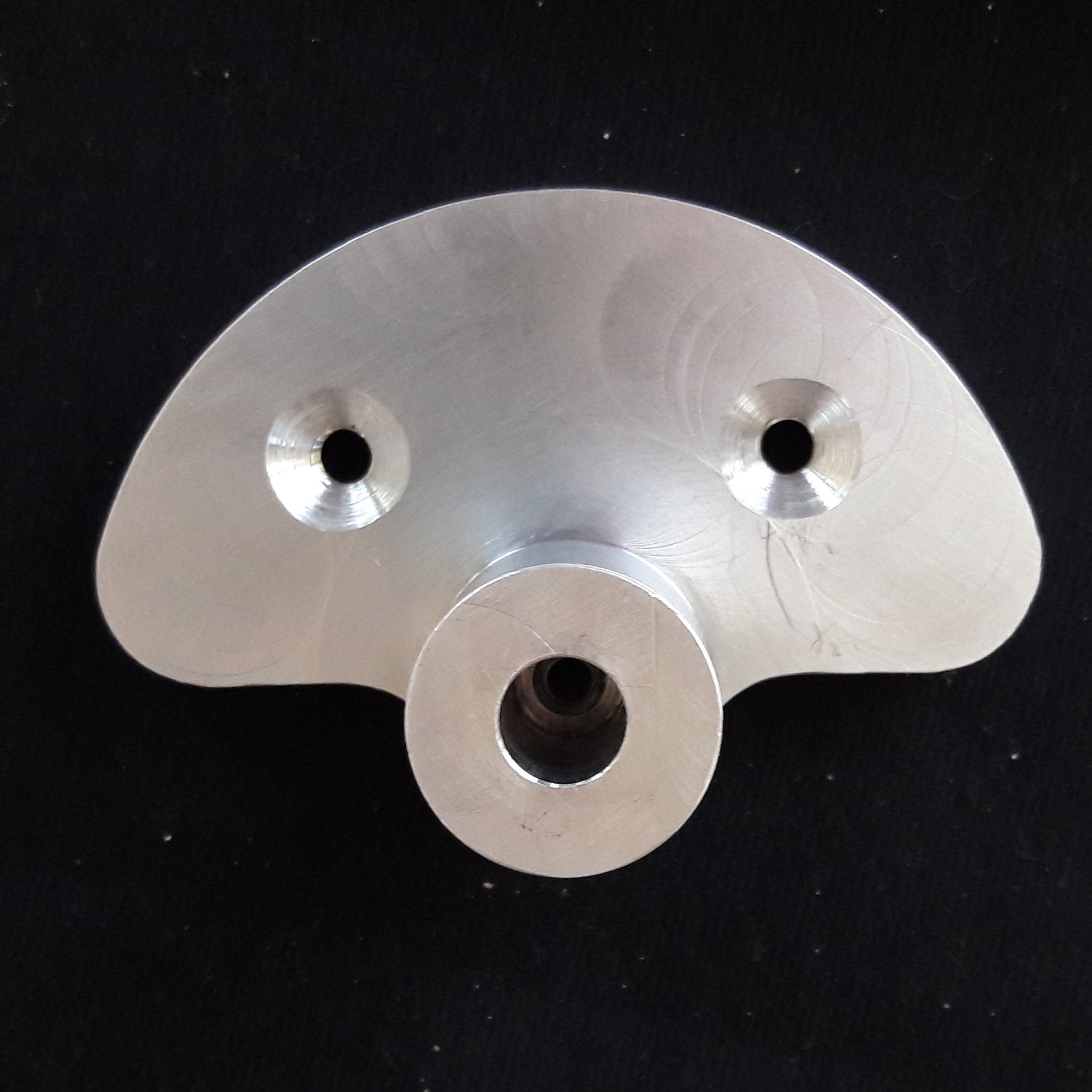
Fig. 6 Rotating part
Before placing the motor block at the top of the torso, optical sensor sensitivity must be adjusted on both sensors. Place the head and supply the sensors with +24V DC. Check that output sensors toggle when the head turns, otherwise tune the yellow screw on sensors to adjust. Then remove the head.
Remove the original black piece fixed on top of the torso, keep the screws. Place the motor block set at the top of the torso and screw it using these screws.
Pass the audio cables into the torso, place the head on the neck and screw it.
Assembly of the limit sensor circuitry
The role of the two limit sensors is to contrain the head rotation between -90°
and +90°, for human-like rotation and to avoid harms on the microphone cables. A
dedicated PCB must be manufactured. Table 4 lists the
needed components, and Gerber files for the PCB are available in the
kemar-hardware repository, in
folder motorized-neck/electronics.
| Item | Qty | Ref | Designator | RS Ref | Farnell Ref | Mouser Ref |
| 1 | 1 | C1 | Capacitor, X7R, 100nF, 50V | 852-3273 | 1469310 | 594-K104K15X7RF53L2 |
| 2 | 3 | D1, D2, D3 | Zener Diode, 15V, 1/2W, 1N5245 | 805-0189 | 1612374 | 512-1N5245BTR |
| 3 | 1 | J3 | Pluggable Terminal Blocks, 8Pos, 3.81mm pitch, Through Hole Header | 220-4888 | 3913120 | 651-1803484 |
| 4 | 1 | J6 | Pluggable Terminal Blocks, 6Pos, 3.81mm, pitch Through Hole Header | 220-4872 | 3913119 | 651-1803468 |
| 5 | 2 | J4, J5 | 3Pos Vertical Pin Header | 745-7068 | 855-M20-9990346 | |
| 6 | 2 | M2, M3 | MOSFET N-Channel 60V, 0.2A - 2N7000 | 214-1276 | 9845178 | 512-2N7000 |
| 7 | 4 | R2, R4, R9, R10 | Resistor, 1/4W, 1%, 10 kOhms | 9341110 | ||
| 8 | 1 | R11 | Resistor, 1/4W, 1%, 470 Ohms | 9339531 | ||
| 9 | 2 | R12, R13 | Resistor, 1/4W, 1%, 1 kOhms | 1457967 | ||
| 10 | 2 | R16, R17 | Resistor, 1W, 10 kOhms | 214-1276 | 279-ROX1S10K | |
| 11 | 1 | U1 | CMOS Quad 2-Input NOR Gate - CD4001B | 662-9483 | 1739899 | 595-CD4001UBE |
Connection to the controller
For this part, you will need:
- A ELMO Harmonica HAR5/60C servo controller
- An encoder cable for Harmonica (CBLIC-BAS-J3)
- A power distribution cable (IA1507/2M)
- An auxiliary +24V DC cable for Harmonica (CBLIC-BAS-J4)
Caution
Before switching the power supply ON, be sure to have connected all the listed elements.
The steps to connect all parts are as follows:
Connect the ELMO Controller (J3 connector) and the motor block set (incremental encoder + Hall effect sensors) using cable CBLIC-BAS-J3.
Connect limit detection PCB (J6 connector) to ELMO Controller (J5 connector).
- J6.1 → +24V DC power supply,
- J6.2 → Power supply return,
- J6.3 → J5.6 (ELMO Programmable input 6),
- J6.4 → J5.8 (ELMO Programmable input return),
- J6.5 → J5.5 (ELMO Programmable input 5),
- J6.6 → J5.7 (ELMO Programmable input return).
Connect the ELMO Controller (J4 connector) to an auxiliary +24V DC power supply using cable CBLIC-BAS-J4. If an auxiliary power supply is not available connect the cable to the +24V DC main power supply.
- J4.1 → +24V DC auxiliary power supply,
- J4.2 → Power supply return.
Connect the ELMO Controller (J1 -RJ-45 plug) to a RJ-45 to 9-pin D-sub adapter using an ethernet cable. The 9-pin D-sub connector is normalized according to CAN protocol.
- J1.1 (CAN H) → 9-pin D-sub, pin 7,
- J1.2 (CAN L) → 9-pin D-sub, pin 2,
- J1.3 (CAN GND) → 9-pin D-sub, pin 3.
Do not forget to solder a 120 Ohms termination resistor between pin 7 and pin 2 of 9-pin D-sub adapter.
Connect the ELMO Controller (J8 connector), available on the side of the controller to the motor phases and main power supply.
- J8.1 (VP+) → +24V DC power supply,
- J8.2 (PR) → Power supply return,
- J8.3 (PE) → If available connect to protective earth,
- J8.4 (PE) → motor protective earth (motor body),
- J8.5 (M1) → motor phase 1,
- J8.6 (M2) → motor phase 2,
- J8.7 (M3) → motor phase 3.
There are no constraints in the pinning of M1, M2 and M3.
Last, connect the limit detector PCB
- J3.1 → L/D wire (white), lateral sensor,
- J3.2 → Q (black), lateral sensor,
- J3.3 → - (blue), lateral sensor,
- J3.4 → + (brown), lateral sensor,
- J3.5 → L/D wire (white), front sensor,
- J3.6 → Q (black), front sensor,
- J3.7 → - (blue), front sensor,
- J3.8 → + (brown), front sensor.
Place jumpers on J4 and J5 connectors between GND and center pin.
Associated software
The designed mechanism has associated open-source drivers that can be installed to control the rotation from a software application. You can install them with:
git clone -b kemar-head https://git.openrobots.org/robots/elmo-axis-libs.git
cd elmo-axis-libs
mkdir m4
autoreconf -vi
mkdir build && cd build
../configure --prefix=/path/to/your/install/folder
make install
The kemar-control repository contains a GenoM3 component using these drivers to control the head rotation in position or in speed via dedicated services. You can install it with:
git clone https://github.com/TWOEARS/kemar-control.git
cd kemar-control
genom3 skeleton -i kemar.gen
./bootstrap.sh
mkdir build && cd build
../configure --prefix=/path/to/your/install/folder --with-templates=ros/server,ros/client/c
make install
The example chapter includes a simple use of this component to Control the rotation of a KEMAR motorized head from Matlab.